
Overview
The nXPico M is a compact development board built around the RP2350A microcontroller with an integrated nRF9151 LTE-M/NB-IoT/GPS modem. It runs neXo’s CODESYS Control pico runtime — see CODESYS › Getting Started.
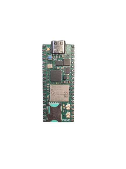
Hardware Specifications
Section titled “Hardware Specifications”| Component | Details |
|---|---|
| MCU | RP2350A QFN-60 |
| Architecture | ARM Cortex-M33 dual-core / RISC-V dual-core, 150 MHz |
| Flash | W25Q32J — 4 MB QSPI |
| Modem | nRF9151 — LTE-M / NB-IoT / GPS |
| RGB LED | WS2812 NeoPixel-compatible — GPIO23 |
| USB | Type-C (USB 2.0) |
| Connector | CN1 — 40-pin Raspberry Pi Pico-compatible |
| Crystal | 12 MHz (Y1) |
Onboard Peripherals
Section titled “Onboard Peripherals”WS2812 RGB LED
Section titled “WS2812 RGB LED”A single addressable RGB LED connected to GPIO23: it is a DWORD output channel in 0x00RRGGBB form — see CODESYS › IO Mapping.
nRF9151 Modem
Section titled “nRF9151 Modem”Connects to the RP2350A over UART0 with hardware flow control lines.
| Signal | Name | GPIO |
|---|---|---|
| UART TX | MODEM_TX | GPIO16 |
| UART RX | MODEM_RX | GPIO17 |
| CTS | MODEM_CTS | GPIO18 |
| RTS | MODEM_RTS | GPIO19 |
| Reset (active low) | MODEM_RESET | GPIO29 |
| Buck enable | MODEM_PWR_EN | GPIO24 |
| Buck PS/SYNC | MODEM_PWR_SYNC | GPIO25 |
CODESYS uses the modem I/O channels as a transparent AT pipe.
Because the modem owns UART0, only one serial port remains for the application — see CODESYS › Serial Ports.
Three analog inputs on the CN1 connector:
| Name | GPIO | CN1 pin |
|---|---|---|
GP26 | GPIO26 | 31 |
GP27 | GPIO27 | 32 |
GP28 | GPIO28 | 34 |
from machine import ADC, Pin
adc0 = ADC(Pin("GP26"))print(adc0.read_u16())
Firmware
Section titled “Firmware”- CODESYS › Getting Started — adding the device in CODESYS
- CODESYS › IO Mapping — digital, analog, RGB LED and modem channels
- CODESYS › Modem — the AT pipe to the nRF9151 (an IEC library for the modem is in development)
- CODESYS › X.509 — device identity, stored in the modem