NX3204 — 4-ch RTD Input
The NX3204 measures temperature using resistance sensors (PT100, PT1000, Ni100, Ni1000) over 4 independent 2-wire or 3-wire channels. A microprocessor linearizes the resistance values and converts them to temperature with ±0.1 °C resolution at 16-bit output.
Hardware
Section titled “Hardware”Connection
Section titled “Connection”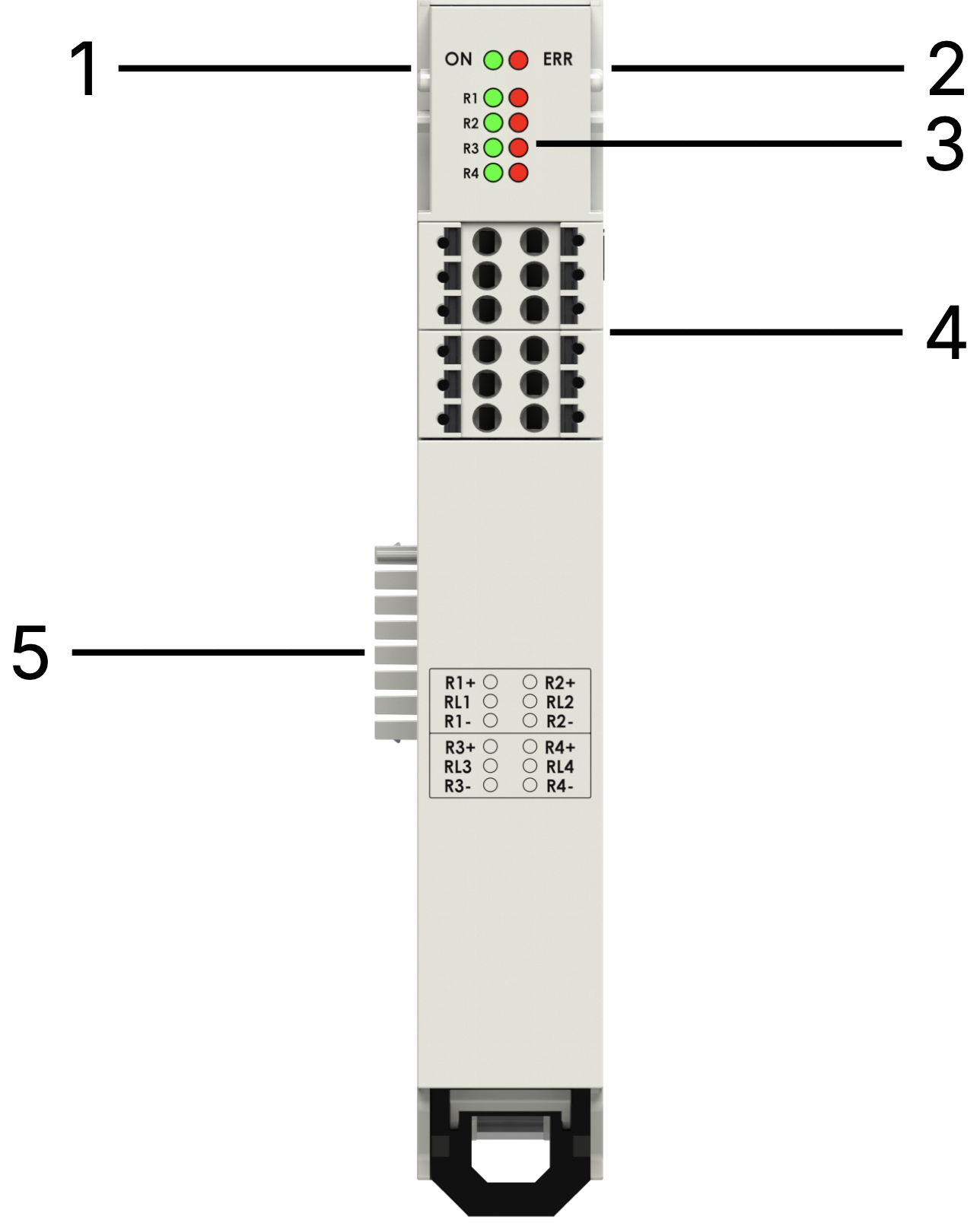
| n° | Item | Description |
|---|---|---|
| 1 | RUN LED | Green — EtherCAT state |
| 2 | ERROR LED | Red — EtherCAT error |
| 3 | I/O LEDs | Yellow — 4 RTD input state |
| 4 | I/O connectors | Removable terminals |
| 5 | Internal Bus | Power supply and EtherCAT bus |
Internal Bus
Section titled “Internal Bus”
RTD Sensor Connection
Section titled “RTD Sensor Connection”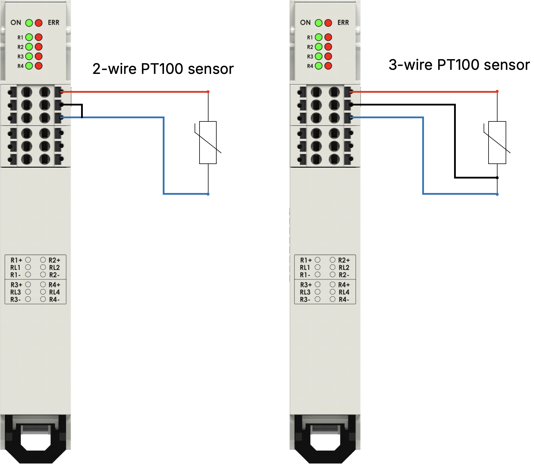
LED States
Section titled “LED States”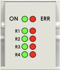
| LED | State | Meaning |
|---|---|---|
| On/Run | Off fixed | Initialization |
| On/Run | Slow blinking | Pre-Operational |
| On/Run | Single blink + pause | Safe Operational |
| On/Run | On fixed | Operational |
| On/Run | Off or fast blinking | Boot |
| Error | On fixed | No connection |
Software
Section titled “Software”EtherCAT I/O Mapping — TxPDO
Section titled “EtherCAT I/O Mapping — TxPDO”| Channel | Value |
|---|---|
| RTD Input 1–4 | INT16 each (temperature × 10, °C) |
SDO Configuration — SDO 8000h
Section titled “SDO Configuration — SDO 8000h”Sensor type selection per channel (default: PT1000):
| Index | SubIndex | Description |
|---|---|---|
| 8000h | 1–4 | Sensor type for channels 1–4 |
Technical Data
Section titled “Technical Data”| Parameter | Value |
|---|---|
| Channels | 4 |
| Sensor types | PT100, PT1000 (default), Ni100, Ni1000 |
| Temperature resolution | ±0.1 °C |
| Update time | 60 ms |
| Module accuracy | 0.5 °C full scale @ 25 °C ambient |
| Resolution | 16 bit |
| Temperature range PT100 | −200 °C … 850 °C |
| Temperature range PT1000 | −200 °C … 350 °C |
| Temperature range Ni100 | −60 °C … 250 °C |
| Temperature range Ni1000 | −60 °C … 180 °C |
| Current absorbed | 30 mA |
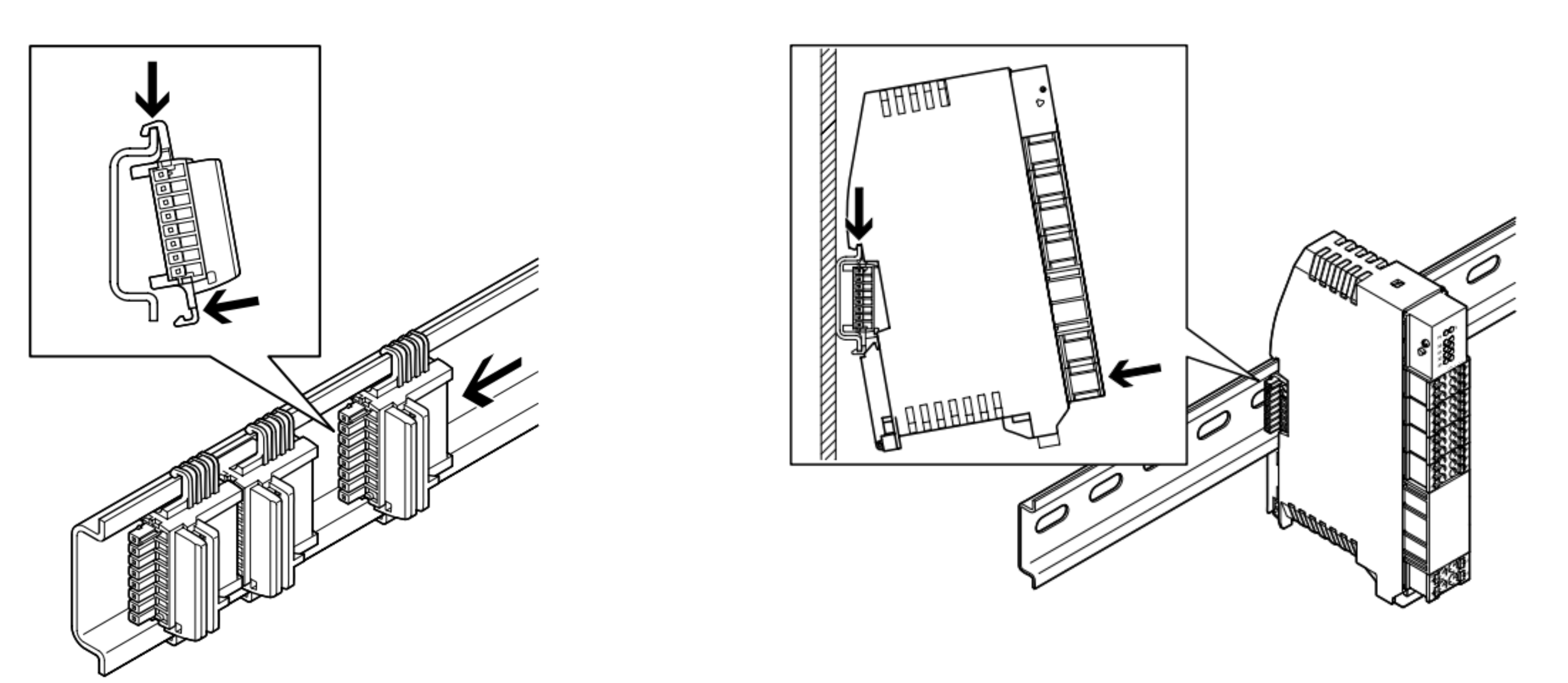
Module Installation
Section titled “Module Installation”Mount on DIN rail (DIN EN 60715). Connect to the left via the T-bus connector. Always power off before inserting.