The NX1016 acquires 16 opto-isolated digital input channels at 24 V from sensors, photocells, and limit switches. Each channel has a 1 ms RC noise rejection filter. Four channels additionally support capture (frequency measurement 1 Hz–2 kHz) and two channels support counter input.
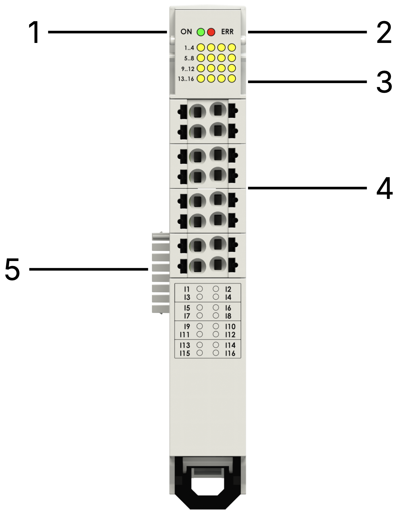
| n° | Item | Description |
|---|
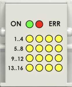
| 1 | RUN LED | Green — EtherCAT state |
| 2 | ERROR LED | Red — EtherCAT error |
| 3 | I/O LEDs | Yellow — 16 digital input states |
| 4 | I/O connectors | Removable terminals |
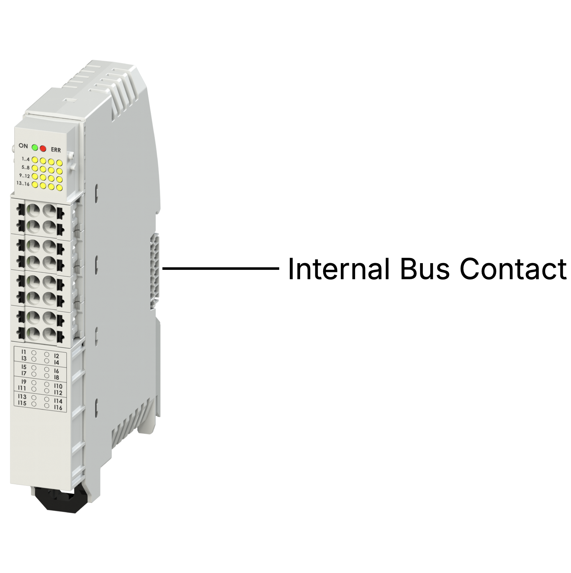
| 5 | Internal Bus | Power supply and EtherCAT bus |
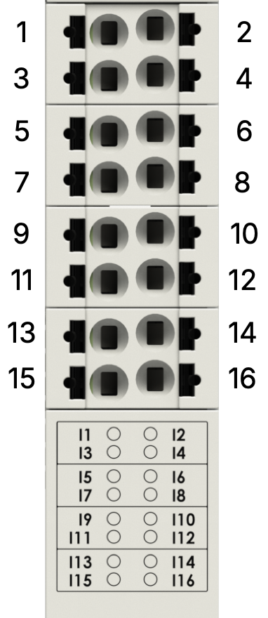
| n° | Function |
|---|
| 1 | Digital Input 1 — Counter Input 1 |
| 2 | Digital Input 2 — Counter Input 2 |
| 3 | Digital Input 3 |
| 4 | Digital Input 4 |
| 5 | Digital Input 5 |
| 6 | Digital Input 6 |
| 7 | Digital Input 7 — Capture Input 1 |
| 8 | Digital Input 8 — Capture Input 2 |
| 9 | Digital Input 9 — Capture Input 3 |
| 10 | Digital Input 10 — Capture Input 4 |
| 11–16 | Digital Inputs 11–16 |
| LED | State | Meaning |
|---|
| On/Run | Off fixed | Initialization |
| On/Run | Slow blinking | Pre-Operational |
| On/Run | Single blink + pause | Safe Operational |
| On/Run | On fixed | Operational |
| On/Run | Off or fast blinking | Boot |
| Error | On fixed | No connection |
Each input channel (1–16) has a dedicated yellow LED: Off = logic 0, On = logic 1.
| Channel | Value |
|---|
| Input 1–16 | bit 0–15 (16-bit word) |
| Frequency 1–4 | 16-bit each |
| Counter 1–2 | 32-bit each |
SDO 8000h — Input filter (1–64 ms, default 1 ms):
| Index | SubIndex | Description |
|---|
| 8000h | 1–16 | Input filter for channels 1–16 |
SDO 8010h — Edge and counter configuration:
| Index | SubIndex | Description |
|---|
| 8010h | 1 | 0: Falling edge / 1: Rising edge (default) on Input 1 |
| 8010h | 2 | 0: Falling edge / 1: Rising edge (default) on Input 2 |
| 8010h | 3 | 1: Reset Counter on input 1 |
| 8010h | 4 | 1: Reset Counter on input 2 |
| Parameter | Value |
|---|
| Channels | 16 |
| Input type | IEC 61131-2, high-side switching, opto-isolated |
| Input voltage range | 0–30 Vdc |
| Logic level ‘0’ | < 5 Vdc |
| Logic level ‘1’ | > 15 Vdc |
| Current ON | 3.5 mA @ 15 V / 5.4 mA @ 30 V |
| Capture frequency range | 1 Hz … 2 kHz |
| Counter min pulse duration | 1 ms |
| Current absorbed | ~50 mA |
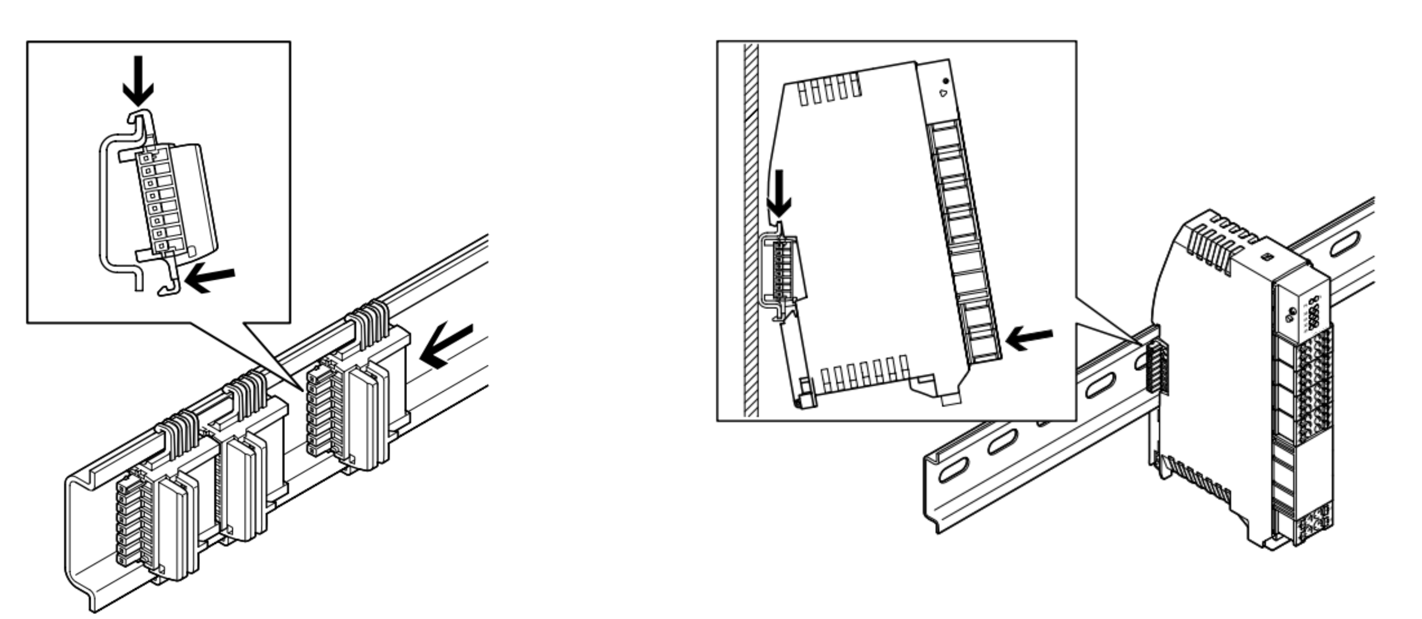
Mount on DIN rail (DIN EN 60715). Connect to the left via the T-bus connector. Always power off before inserting.