NX0001 — EtherCAT Slave Coupler
The NX0001 module enables nXIO I/O modules to communicate with an EtherCAT master via the EtherCAT protocol. Thanks to its dual EtherCAT port it supports daisy-chain connections, allowing multiple couplers to extend the I/O capacity of a single master.
Hardware
Section titled “Hardware”Connection
Section titled “Connection”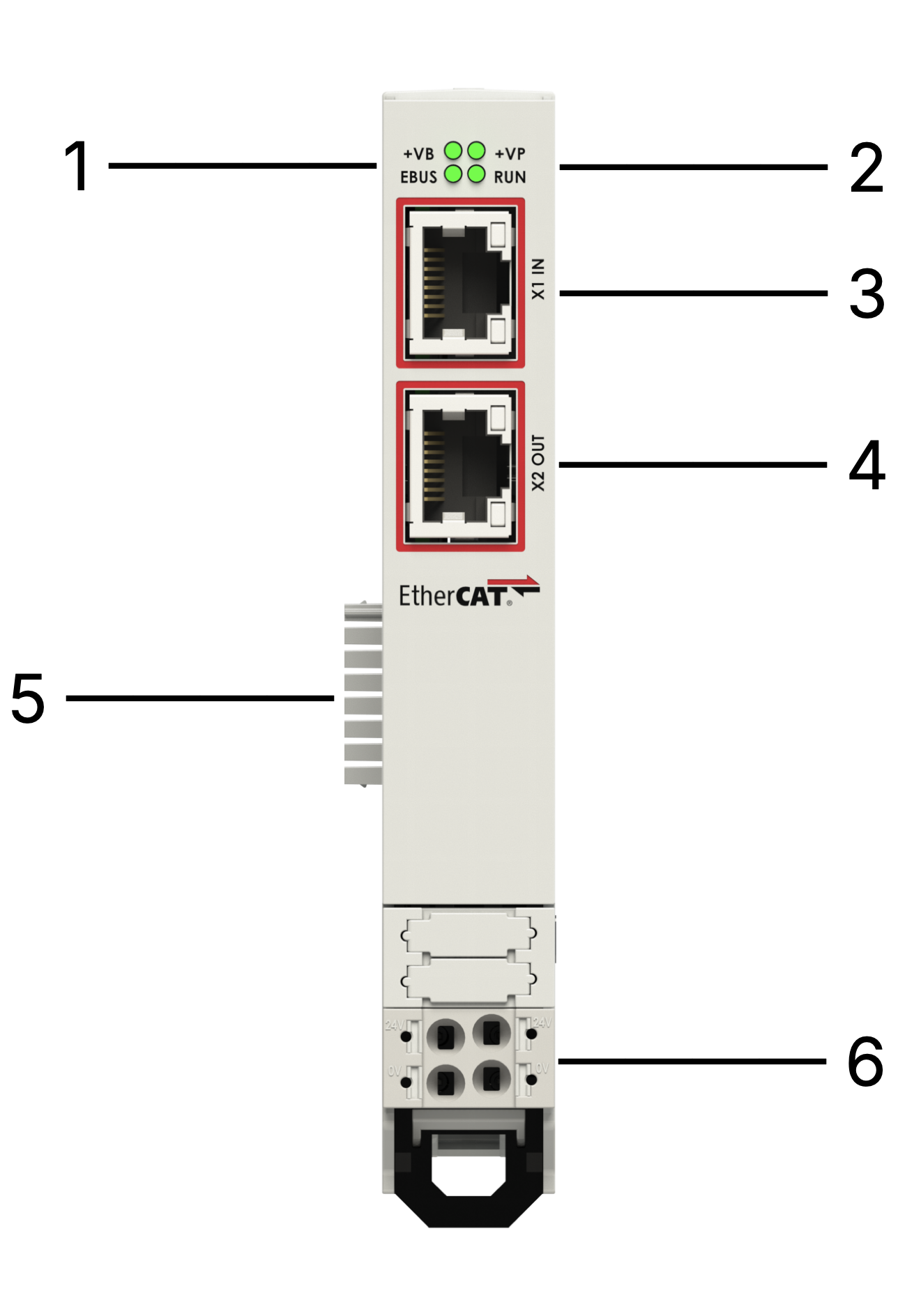
| n° | Item | Description |
|---|---|---|
| 1 | EBUS and +VB LEDs | Status LEDs for EBUS and +VB |
| 2 | RUN and +VP LEDs | Status LEDs for RUN and +VP |
| 3 | EtherCAT IN Port | RJ45 connector |
| 4 | EtherCAT OUT Port | RJ45 connector |
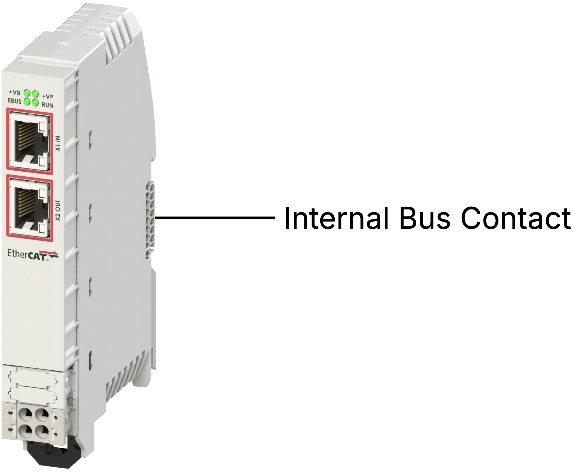
| 5 | EtherCAT Internal Bus | Internal T-bus connector |
| 6 | 24 Vdc Power Supply | Removable power terminal |
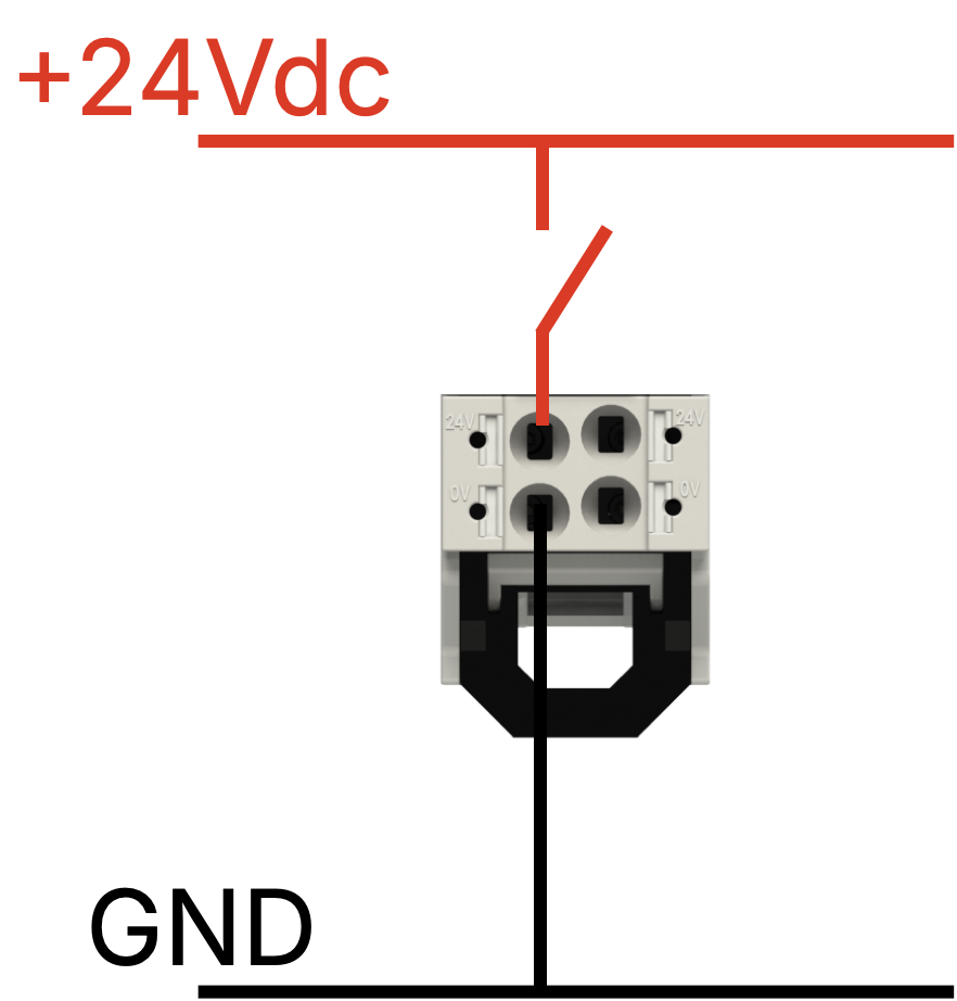
Power Supply
Section titled “Power Supply”The NX0001 requires 24 Vdc (±5 %) protected against phase reversal by a self-resetting fuse. Use a delayed fuse of max 2 A for overcurrent protection.
Internal Bus
Section titled “Internal Bus”The 24 Vdc input provides 5 Vdc (galvanically isolated) to all connected NX I/O modules via the internal bus.
LED States
Section titled “LED States”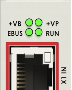
| LED | State | Meaning |
|---|---|---|
| +VP | On | 24 Vdc present |
| +VB | On | 24 Vdc present on internal bus |
| EBUS | On | EtherCAT bus active |
| On/Run | Off | Initialization |
| On/Run | Slow blinking | Pre-Operational |
| On/Run | Single blink + pause | Safe Operational |
| On/Run | On fixed | Operational |
| On/Run | Off or fast blinking | Boot |
Technical Data
Section titled “Technical Data”| Parameter | Value |
|---|---|
| Width | 19 mm |
| Height | 124 mm |
| Depth | 76.5 mm |
| Supply voltage | 24 Vdc (−25 % … +30 %) |
| Current absorbed | 30 mA |
| Power supply isolation | 500 V |
| Connection type | Push-in spring, 5 mm pitch |
| Conductor section | AWG 24–16 |
Software
Section titled “Software”Module Configuration
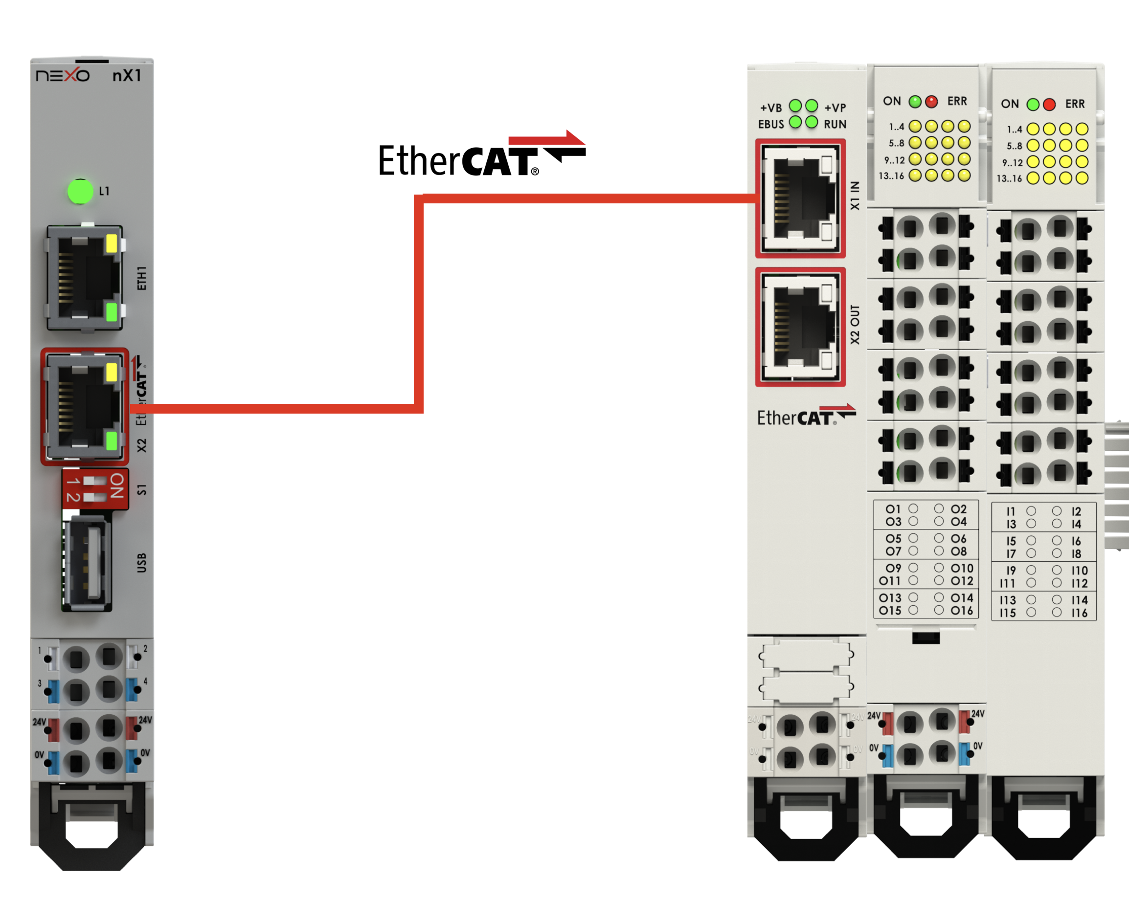
Section titled “Module Configuration”The following procedure uses the neXo nX1 or nX8 as the EtherCAT Master and CODESYS V3 as the development environment.
Example setup: NX0001 coupler + NX2016 + NX1016 connected to nX1.
Step 1 — Install .xml configuration file
Section titled “Step 1 — Install .xml configuration file”Open CODESYS V3, go to Tools → Device Repository, click Install and select the .xml file received from neXo.
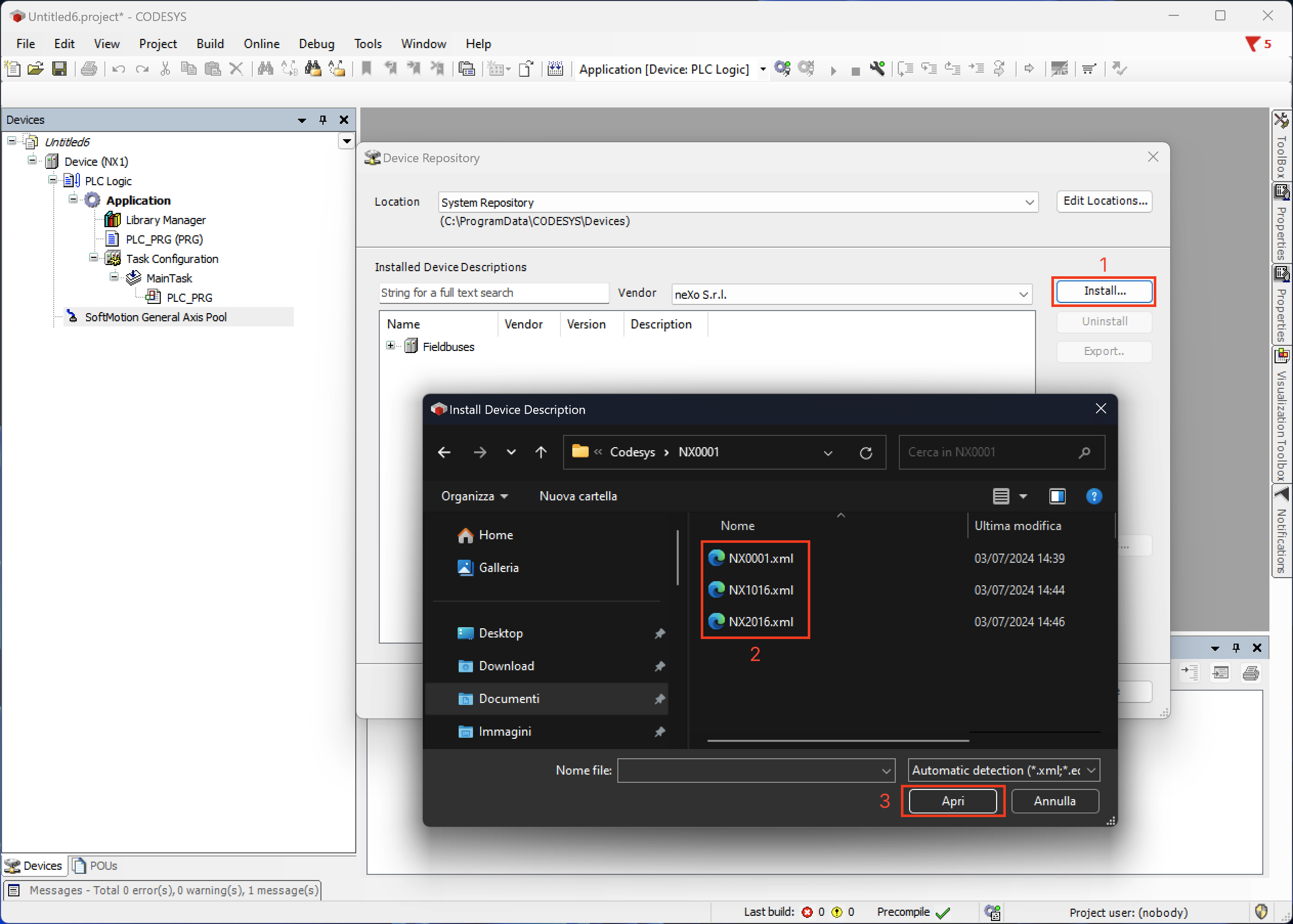
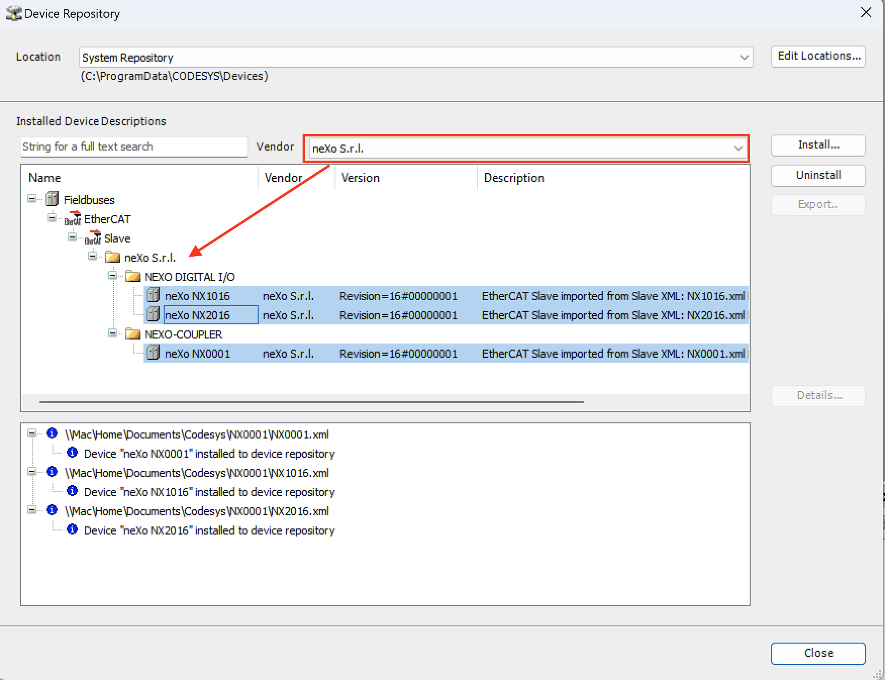
The device will appear in the neXo device list.
Step 2 — Add EtherCAT Master
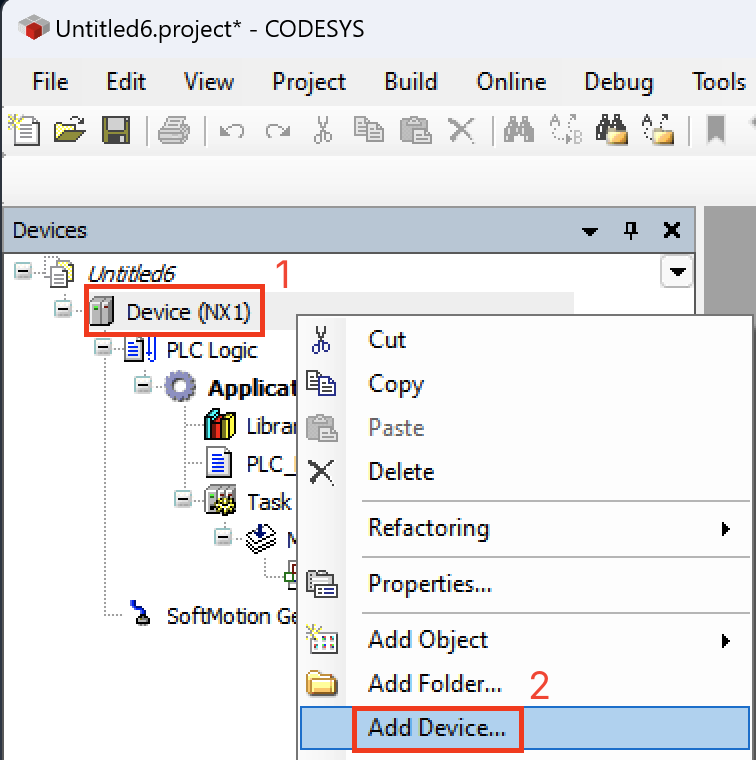
Section titled “Step 2 — Add EtherCAT Master”Right-click the master controller in the device tree and select Add Device….
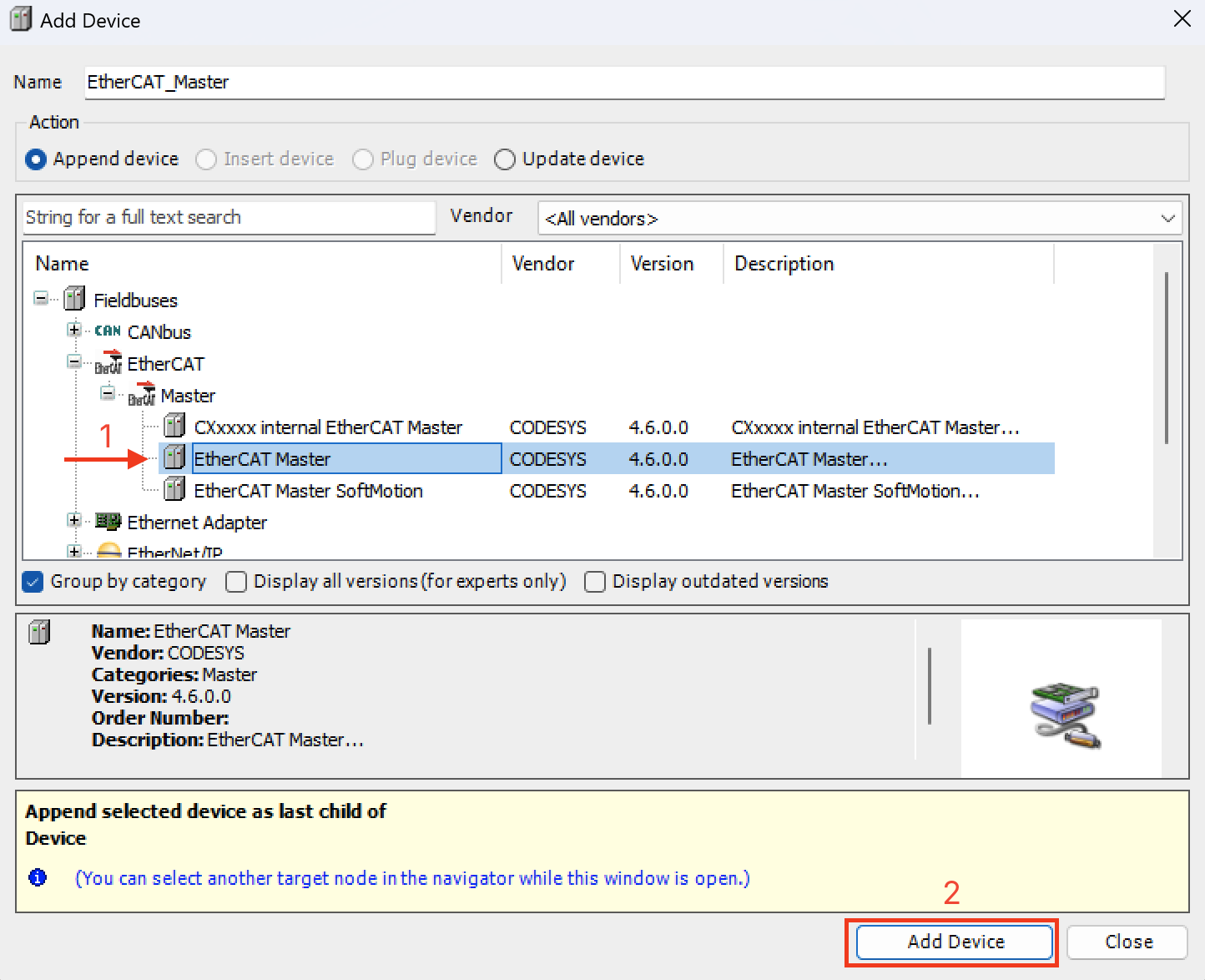
From Fieldbuses → EtherCAT → Master, select EtherCAT Master and click Add Device.
Step 3 — Add NX0001 Slave Coupler
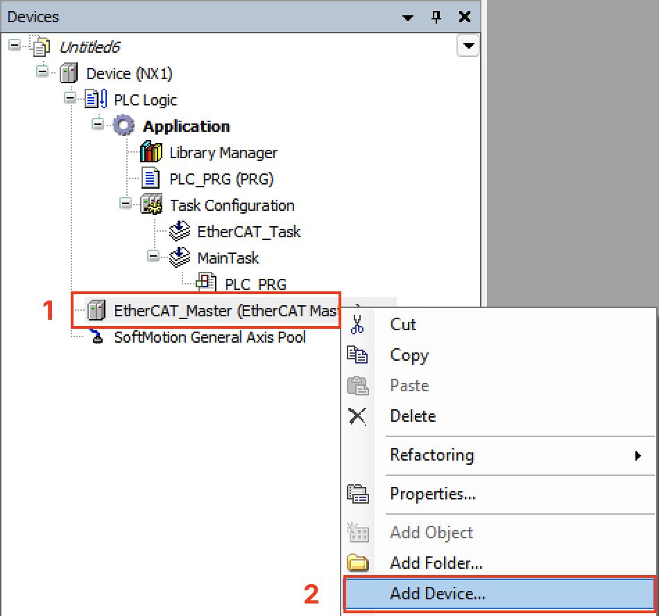
Section titled “Step 3 — Add NX0001 Slave Coupler”Right-click the EtherCAT Master and select Add Device…
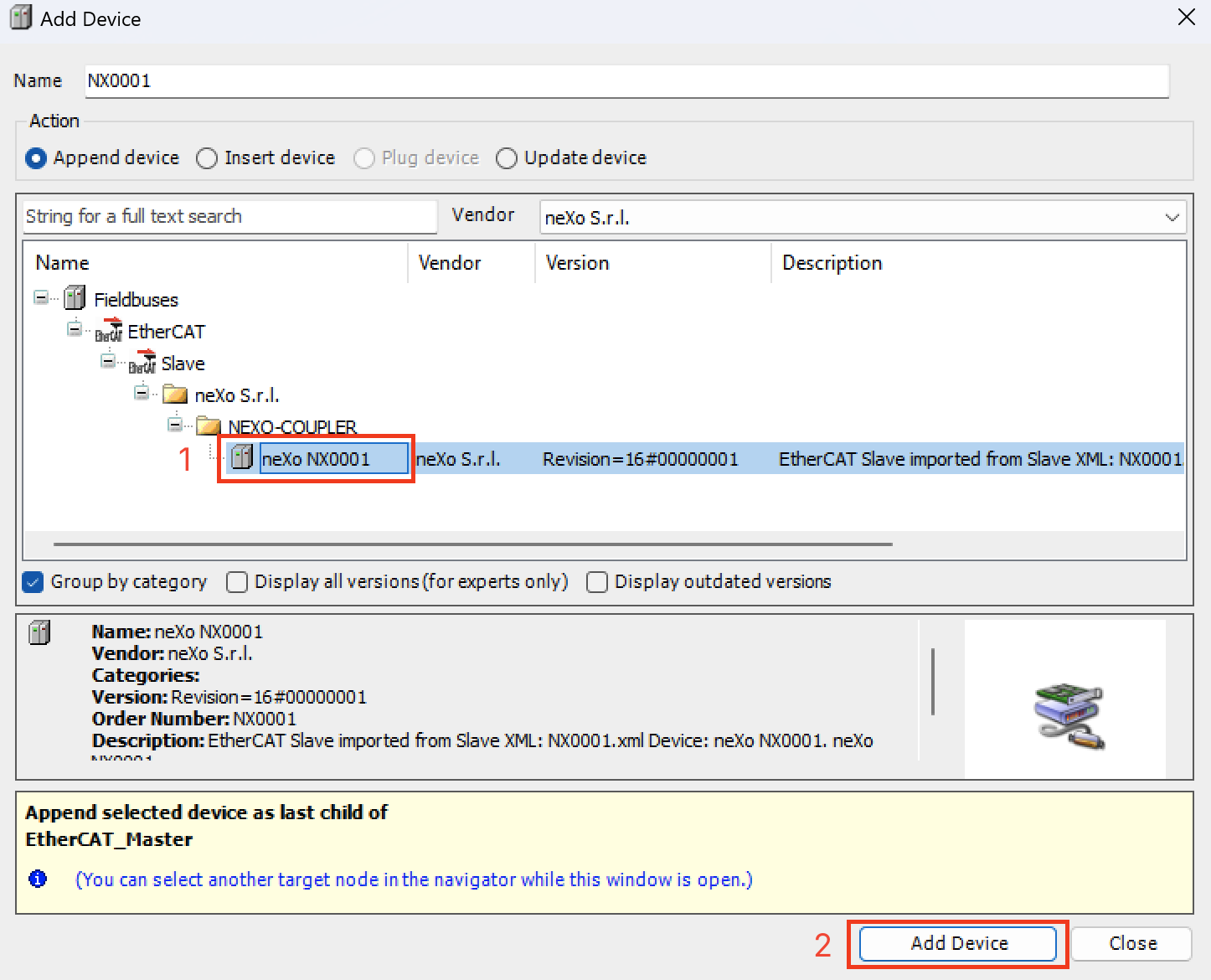
From Fieldbuses → EtherCAT → Slave → NEXO-COUPLER, select neXo NX0001.
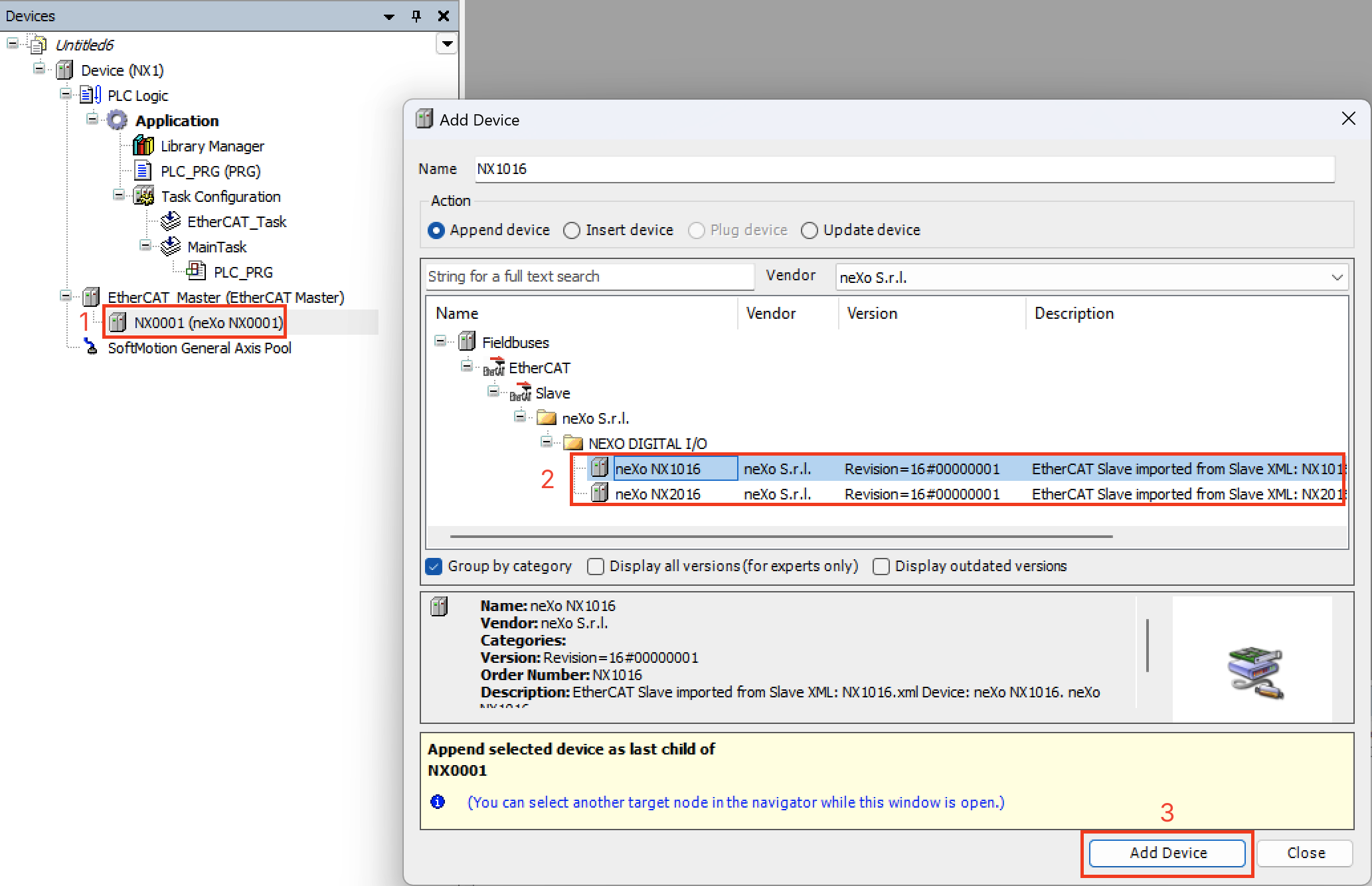
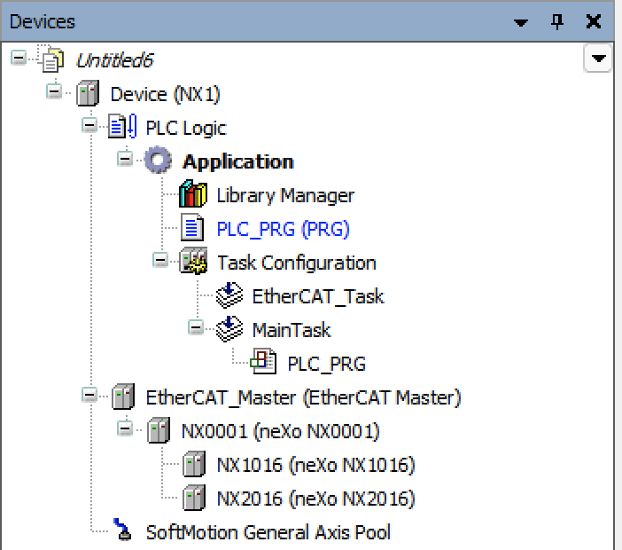
Step 4 — Add NX I/O Modules
Section titled “Step 4 — Add NX I/O Modules”Right-click the NX0001 object and select Add Device… to add the desired I/O modules.
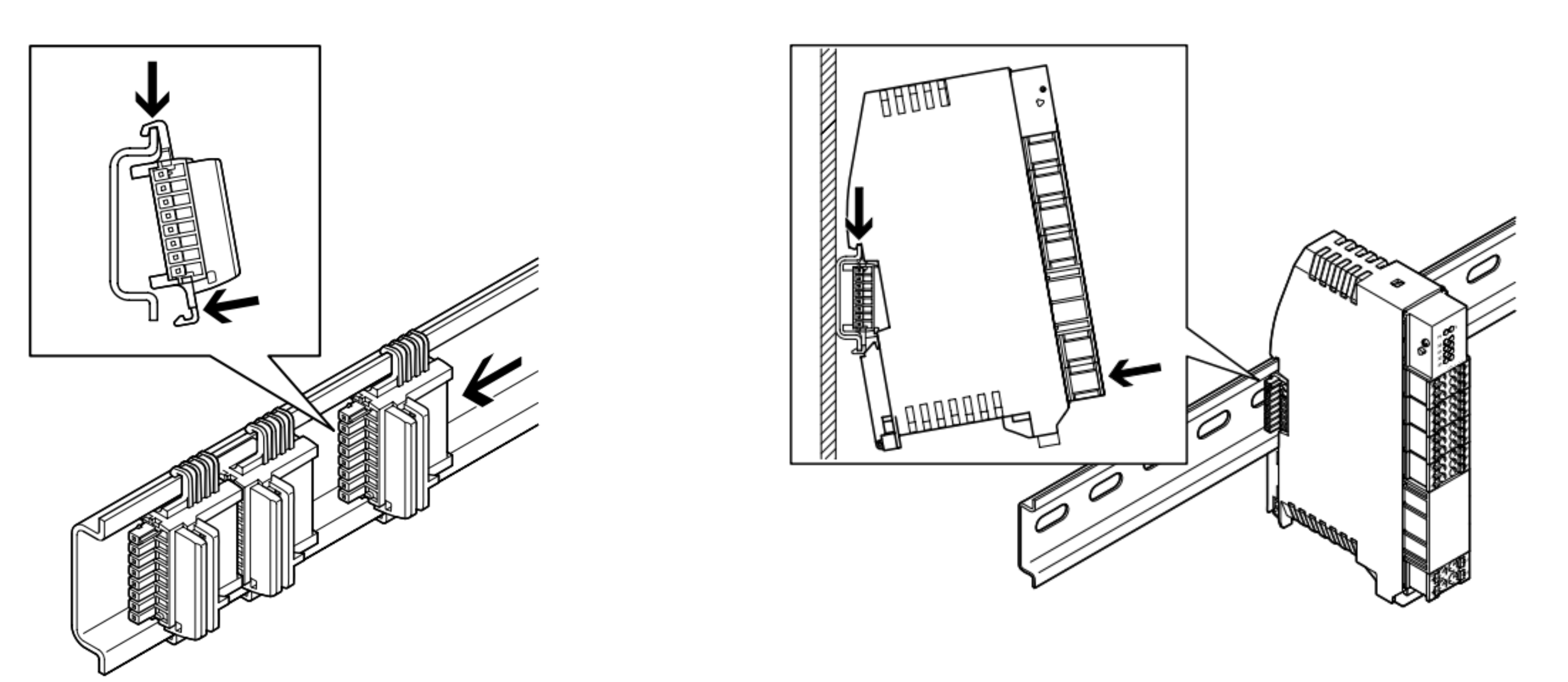
Module Installation
Section titled “Module Installation”Mount the NX0001 on a DIN rail (DIN EN 60715) to the left of the I/O module chain. Connect modules via the T-bus connector. Always power off before inserting.