
Hardware
Connection
Section titled “Connection”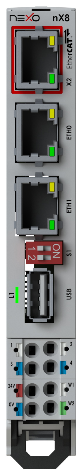
| Symbol | Function |
|---|---|
24V | Power supply +24 VDC / @1.5 A |
0V | Power supply 0 VDC |
W1 W2 | Watchdog relay output |
1 | CAN High (CODESYS CAN0) |
3 | CAN Low (CODESYS CAN0) |
2 | RS485 TX+ (CODESYS COM3) |
4 | RS485 RX− (CODESYS COM3) |
USB | USB Host — external memory or CODESYS License Dongle Key |
S1-2 | Switch — CAN 120 Ω termination (ON = closed) |
S2-1 | Switch — RS485 120 Ω termination (ON = closed) |
ETH1 | Ethernet — real-time |
ETH0 | Ethernet |
X2 | Ethernet local bus ET1100 EtherCAT |
Power Supply
Section titled “Power Supply”Input: +16 Vdc to +28 Vdc.
| Pin | Signal | Min | Nominal | Max |
|---|---|---|---|---|
24V | +V | 16 V | 24 V | 28 V |
0V | GND | — | — | — |
Front LED
Section titled “Front LED”| Color | Meaning |
|---|---|
| White | Booting OS |
| Yellow | CODESYS application STOP or not loaded |
| Green | CODESYS application RUN |
| Red | CODESYS application EXCEPTION |
| Off | No power |
Retentive Memory
Section titled “Retentive Memory”Variables declared RETAIN are automatically saved to micro UPS-backed memory. Maximum: 128 kB.
(* In a POU *)VAR RETAIN    iCounter : INT;END_VAR
(* In GVL *)VAR_GLOBAL RETAIN    gvarRem1 : INT;END_VAR
The micro UPS automatically saves retain data when input voltage drops below 16 VDC. The front LED turns off during this process to conserve power.